| The
Fixed and Floating Fastener Formulas are Not Just for
Fasteners.
Nearly all assemblies fall into the
categories of either fixed or floating features. A floating
feature assembly might be a shaft floating within two
bushings. Where a part floats between multiple features, the
floating fastener formula will usually apply. The ASME
Y14.5M-1994 standard gives the floating fastener formula as H
= F + T where:
H is the
clearance hole's maximum material condition (smallest
limit of size)
F is the fastener's maximum material
condition (largest limit of size)
T is the positional
tolerance |
For floating type assemblies, just
substitute the internal feature's smallest size (MMC) for H,
the external feature's largest size (MMC) for F and the
allowable positional tolerance (T) may be
calculated.
When a screw or dowel pin is assembled, it
becomes "fixed" to the mating part. Therefore, the fixed
fastener formulas work whenever features are "fixed" on mating
parts. These assemblies include bosses fitting into holes,
tabs fitting into slots, etc. The ASME Y14.5M-1994 standard
gives the floating fastener formula as H = F + T1 + T2
where:
H is the
clearance hole's maximum material condition (smallest
limit of size)
F is the fastener's maximum material
condition (largest limit of size)
T1 and T2 are the
positional tolerances for the holes and
fasteners. |
For fixed type assemblies, just
substitute the internal feature's smallest size (MMC) for H,
the external feature's largest size (MMC) for F and the
allowable positional tolerance (T1 + T2) may be calculated. T1
and T2 need not be equal and may be distributed to reflect
process capability of the processes being used. For the
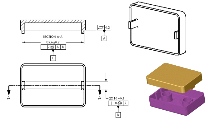
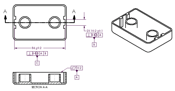
assembly shown below:
|

|
|
The two tabs
fitting into the two slots is a fixed fastener assembly.
MMC of the two tabs is 10.1. MMC of the two slots is
also 10.1. Therefore H = F + T1 + T2 or 10.1 = 10.1 + 0
+ 0. |
 |
|
| |